
Building the Rans S-21, Episode 2, The Vertical Stab - Pt. 1
Updated: 17 hours ago
If you need a cure for insomnia, you can start the series here.
The next major sub-assembly to tackle is the Vertical Stabilizer (VS). It is very similar to the Rudder, except for where it is different. For starters, there is no skin rolling with this structure. Secondly, there are considerably more parts in the VS.
I am used to the way that Van's does their Vertical Stabs, I have built several of them (RV-7, RV-12, RV-9, RV-8). On the RVs, the VS stab skin is all one piece and the sides of the fin are mostly straight. On the S-21 there are two flat side skins and a folded L/E Skin that covers the front. In many ways, this is a more manageable configuration and is probably necessary due to the fact that the sides are not flat, there is a curve to them.
8/29/26 - The first thing that I noticed is that the side skins looked weird. I couldn't figure it out at first, but then I noticed that several of the holes had something shiny on them.

At first I thought that maybe they hadn't been drilled all the way through, but when I poked it with a scribe, the piece fell out and the hole was open. I found that the easiest way to clean them was to just touch it with a #30 reamer.
After reading the instructions for the VS, all 10 steps, I was confused by the instruction to "Cleco the side skins to the frame assembly. Do NOT cleco to the FWD Spar at this time." It was confusing because there were no holes in the side skin at the forward spar to put a cleco in. Not only that, but there were no holes in the flanges of the forward spar either. OK, no big deal, I just have to cleco everything together and use the L/E skin as a drilling guide for the side skin and spar.
The next thing that I found, was that the rear spar has no holes for the lower hinges. The holes are in the two doublers that sit on it, but not in the spar. OK, no problem, I just have to drill those holes in the spar using the holes in the doublers as a guide. Well, OK, a little bit of a problem, the instructions never say anything about drilling anything.
This is going to take some more research.
Update, I was looking at the wrong spar. I was looking at the front spar and the hinges go on the aft spar. OK, no problem with hinges, but why are those holes in the doublers?
9/4/26 - 9/7/26 - Before I can learn too much more, I have to prepare the frame parts so that I can cleco them together and see how the skins fit. The only thing the instructions say is to flute the ribs so that they lay flat on a table. Oh, that is probably all that is really needed, but not all that I am going to do.
As stated elsewhere, the parts that come from Rans are in much batter shape than the ones I am used to working on from Van's. On the Van's parts it is necessary to not only deburr the punched holes, but to smooth the edges to eliminate any sharp spots that can create stress risers that can lead to cracks. The general guidance from Van's is that if the side is smooth enough that you can run your finger along it without drawing blood, it is smooth enough. The Rans parts meet that criteria out of the box, but I look for something a little bit better. Fortunately, the parts are of such good quality to begin with that it doesn't take long to get the finish that I feel is necessary on my airplane.
First, a note about deburring. Deburring is the process of removing the little bit, or in some cases not so little bit, of metal left around a hole, usually on the exit side, as a result of punching, drilling or reaming operations. These burs cause the two sheets being joined to be held away from each other a tiny amount when riveted. Over time, with motion and vibration, the burr can break off which leaves a gap in the riveted joint that can allow movement which can eventually cause the rivet to work loose, meaning that it is not doing its job in carrying the load.
In the case of the Rans parts, there isn't a burr per se, in that there isn't any metal sticking up from the surface. What is does, on the other hand is have one side where the edge of the hole is very sharp. That probably isn't an issue, and many, if not most S-21 builders probably use the parts right out of the box. In my case, it just makes me feel like I need to make it a little better.

The photo above shows one of the holes in one of the doublers magnified to show the detail. If you look at the rim of the hole, you can see that there is no break to it and it is a sharp line. When you run your fingers over the hole, you can feel this sharp edge. The same sharp edge appears on the side of the piece as well, more on that later.

The photo above shows the same hole after being gently hit with a deburring tool. I want the sharpness gone, but I don't want the hole countersunk.
There are a number of tools made for deburring. One can use anything from a drill a few sizes larger than the hole being deburred to custom made deburring tools. I have quite a few, and have used many of them. The ones that seem to work best are countersink cutters in some kind of holder allowing it to be rotated by hand.

Countersink cutters seem to work the best for deburring and I find that a single flute countersink of the correct size is my favorite tool to use. Multiple fluted countersinks, and other deburring tools, can tend to chatter, even when turned by hand and that leads to a jagged hole that is not good.

The hand tool shown above is very handy for turning the countersink. One must be careful as even by hand, this will take off a lot of material quickly if you're not careful.

Frequently, particularly when I want to remove the minimum material possible, I will put the cutter in the extension and just twist it with my fingers. This allows much greater control over how much material is removed.
I frequently see people using something like this chucked into a power screwdriver or other similar tool and it makes me cringe. It is very easy to remove way too much material very quickly like that, possibly ruining the part being worked on. For someone who knows what they are doing and has a very light touch, that may work, but I don't trust myself to do it that way. In this case, there is so little material to be removed that a power tool is just not needed.
Now that we have the holes cleaned up, we need to turn our attention to the edges. The same basic principle applies, but the method of correcting is a little different.

It doesn't show up so well int he picture above, but, aside form the sharp edge we talked about earlier, the surface is a little rough with marks left by whatever was used to cut the part out. Once again, it would probably be OK to use right out of the box and even more so by just knocking down the sharp edge. I just can't bring myself to do that.
I found a way to do this that allows me to quickly get the part to a condition where I am comfortable using it. I secure the part in a vise, where possible, or just lay it flat on a table when not and take a few passes with a file to get the irregularities and high spots off of the side. From there, I use a Scotch Brite wheel chucked in a drill press to remove the marks from the file.

That results in a part that is very smooth and allows me to sleep at night.
Now that I have a good start on part prep, it is time to start putting things together to see what they look like assembled. The first time I tried this I got the first side skin clecoed on only to realize that I had forgotten to install the nose ribs forward of the front spar, so I had to take it all apart again and do that. The second time went a little better, or so I thought.

Now it is time to cleco on all the skins. That went reasonably easily, though the L/E skin did take a little more effort, largely because it only attached to the ribs, that leaves it a bit floppy at the spar.

With the skins clecoed on, I am getting a better idea of what will be required to drill the side skin and forward spar. Since there is so little, at this moment, holding the L/E skin on, it doesn't want to stay down on the spar very well at all. It quickly became clear that I am going to need a bigger boat, no, wait, I will need more shot bags to make this work.
All, or at least most, of the video I have seen show people using 5 lb shot bags to weight things down for drilling and riveting. I ended up with two 25 lb bags of lead shot. I already made 5 5 lb bags, but feel that greater quantity is required. With the last bag of shot I am going to make either seven 3 lb bags and one 4 lb bag, or maybe five 3 lb bags and two 5 lb bags. I don't know, I'm just looking for more bags. I really need to get that done before I start drilling the front spar.
Next I need to cut off the extra bits of skin they leave at the front edge. I have no idea what purpose that serves nor why they leave it on, but it has to be removed. I wanted to wait until I had it clecoed together to see if it looked like it would help and I would then cut them off after I drilled, but I think they should be cut off first. Also, I need to break the edges on the L/E skin and after looking at it, I think it would be better to do that before drilling.
The last big thing that hit me happened when I was explaining the whole thing to Carl. As I was looking at it, I saw that the mount holes in the three layers of material on the aft spar didn't line up at all. Carl thought maybe I had them in the wrong order, but I didn't see how that could be possible.

Sadly, for me, with just one glance at the drawing he figured out what I did wrong. I had put that stack of parts on backwards.

Note that the sticky down bits should be angled in the same direction, not towards each other. The aft spar, the one on the left above, is facing the wrong way. Unfortunately, I clecoed them on from inside the frame, so I have to take most of it apart again to flip it over.
I'm glad I didn't do what the instructions said and rivet all this together before tackling the skins. That would have made me very angry. Once again, the best solution is to study what information they give very closely and a strong help to that is to take your time. So I have to uncleco it a few times, at least I will know it is together correctly when I do rivet it.
I had to remove one of the side skins and uncleco the lower rib, but I was able to get all of the doublers out and put into the correct orientation. Once that was done, surprise, surprise, all of the holes lined up.
Once that was done, I pulled the L/E skin off so that I could break the edges on the long long edges. I went back and watched the Outbound 300 video on the VS and he did that before drilling also.
This is the first time that I have done this and it is one of those things that they make look really easy in the videos, but when doing it yourself, it's not quite so easy. I tried on a piece of scrap material first and that worked pretty well. Of course, when I went to the actual skin, it wasn't quite so easy. I got a good result, but it could have been better and, since this will get done a lot on skins for this airplane, I will hopefully do better on future skins.
Once all of that was done, it was time to put the L/E skin back on the frame. After getting it all clecoed back into position it was time to put it up on the blocks and get it leveled out. This one is a little harder since the sides are not flat so that it is necessary to have some way to hold the front and back from moving. Fortunately, I found a small pack of wood tapered shims and I was able to wedge those in to get the whole thing level.
To check for level, they tell you to use the tooling holes in the two end ribs. It is easiest to put a couple of clecos in those holes and then rest a level on the clecos. The problem with this is that the reference holes are somewhat recessed from the sides of the skins and I couldn't get any of the levels I have to fit in there. Finally I got a piece of aluminum rod that was in the scrap pile and zip tied a torpedo level to it.


After I had checked and rechecked for level 50 or 60 times, I very timidly drilled the first hole. Get this wrong and there are several parts that will have to be replaced. I continued to check both ends for lever several times throughout the drilling process and fortunately, nothing moved.

I was a little bit concerned about how the final skin lap would turn out since it puckered a lot when left to sit by itself. Shot bags helped to corral it, but the only thing that seemed to make it sit flat was to hold it at just about every rivet hole. So, as I was drilling, I was pushing down on the skin on both sides of the holes with my fingers. That seemed to work well and I am quite pleased with the way the skin fits now.
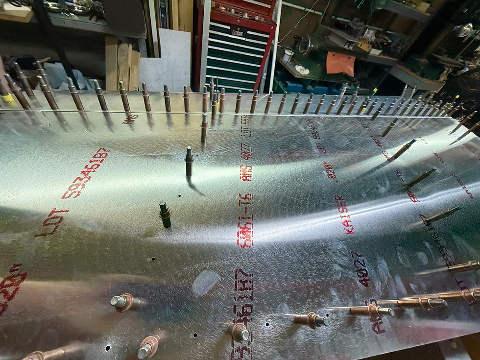
Next I need to drill the other side and then I get to take it all apart again to deburr and apply ProtectaClear, then it will be time for final assembly, making sure to get all of the parts correctly oriented before riveting.
Part 2 available here.


Comments