
Building the Rans S-21 - Episode 1, The Rudder - Pt. 1
Updated: Aug 30
With the inventory almost complete, I finally get to start on the fun part. It took some time to work through all of the hardware, but I think it will be time well spent int he long run.

Pictured above are almost all of the Rivets, Bolts, Nuts, Washers, Screws and other hardware for the whole kit. I do have some separated out for the wing kit, but this is mostly all of it.

The instructions have you start the assembly process with the Rudder. Since this is the smallest and least expensive part of the airplane, it is a good starting point. As mentioned previously, most kit manufacturers make the whole tail one kit, some even adding the aft fuselage "cone" to the tail kit. Rans makes the tail in three kits; Rudder, Vertical Stab, Horizontal stab / Elevator.
I am purposely starting construction before I build my long term building table. I have a work bench in the back of the hangar that is big enough for at least the rudder and vertical stab, and maybe the flaps and ailerons as well. This allows me to get a feel for the construction techniques for this airplane and get a feel for the layout of the hangar. I will eventually need a much larger table, but this works for now.

There are relatively few parts in the rudder, which also helps make it a good place to start. What you see there holding up the parts, is an old steel work bench with a solid core door on top of it and a solid core fire door on top of that. But wait, there's more, well there will be later.
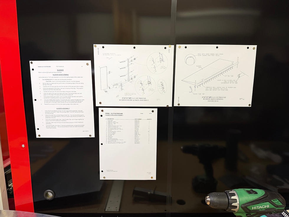
The bench that I am using at the moment is behind a couple of steel Craftsman storage cabinets that I have a bunch of the stuff that I use in the operation of my RV-8. That makes a useful place to put the pages from the three different manuals that pertain to the rudder. A few magnets and they stay right where I want them but can be taken down easily when needed. The only problem is that the 8 1/2 X 11 pages they are on are hard to see from across the table. For that purpose, I bought a 32" monitor for my MacBook Neo so that I can enlarge the page or zoom in where needed.

The bench is under the loft so there is a lower "roof" over it. That comes in handy because it is a good place to hang lights from and I can put light wherever I want it.
The instructions have you start by rolling the leading edges of the rudder skin. More on that later. Since I needed a few supplies I didn't have, I figured I would start on the frame and then come back to rolling the skin.
For the frame, they have you press the oilite bushings into the hinges. To accomplish this I used an arbor press. Many people in videos that I have seen, use a vise to do this. While that works, a press is a more elegant solution.

In this case, the hinge was taller than the anvil on the press, so I just used a socket to set it on. These go in pretty easily and don't require a lot of force, so this method works. The process of pressing the bushing in can cause it to get squeezed slightly so that a bolt won't fit through the hole. In the factory build video, the guy running the class just told people to use a file to clean out the holes. I thought that was a pretty poor solution, though it obviously works. Fortunately the instructions do say to ream the hole and that's what I did. Since it is a 3/16" bolt, I used a .1875" reamer to clean out the holes. Since this is where the mount bolts go, and there is very little room to get the bolts, let alone tools, in there, it is important that they slip in pretty easily.
From there I started on the preparatory work on the ribs and spar. The parts that come out of the box from Rans are in very good shape and need very little additional work. There is a slight burr on the exit side of the holes and a slight wire edge on the sides of the parts where they were cut. Many people probably just put them together without worrying about those and that may be OK, but not for me. I wanted to deburr the holes and smooth the edges. In reality, I probably should have waited until after I drilled the right side of the frame to do that, but it was something to do at the moment.
8/15/22 and 8/16/22 - I got what I needed and am ready to have a go at rolling the leading edges of the skin. The guy behind the Outbound 300 channel on YouTube has made a lot of refinements and tools that I think will be helpful. One of the first ones that I grabbed on to was the tools he made for holding the pipe used to roll the skin. He was kind enough to post the .stl files on his web site, so I downloaded and then printed them out.

The instructions just tell you to push down on the tube while you rotate it and that two people will likely be necessary. After seeing a couple of people doing it this way, including at the factory, I really wanted a better way.
As mentioned earlier, on top of the fire door are a few shelves that just happen to be 1" MDF that I was able to fasten those tools to. I was a little worried that they might wander all over the table top, but they worked out well. This is a critical step and if it is not done correctly, the skin is ruined an must be replaced. No pressure.

It took a good bit of time to get all of that set up, so by the time I got around to giving it a go it was pretty late in the afternoon, so I called it a day. The next step will be to finish the roll on the first side, then do the other side which should go more quickly.
8/22/26 and 8/23/26 - The first order of business today was to finish the leading edge rolling. I put the skin back on the table and ran the pipe through the clamps and clecoed it back to the skin. This time I put some paper between the table / shelf and skin to protect the skin and help things slide a little better. After rolling the first edge a little more, I ended up with a pretty good finish. On to the other side.

Once the leading edges were rolled, it was time to get back to preparing for installation of the frame. After reading through the instructions, I decided I didn't like the way they have you put it together, so I wrote my own instructions.
For instance, once they skin is rolled they tell you to rivet the hinges and ribs to the spar and then put that assembly into the skin. Next they want you to cleco and rivet the left side, the pre-punched side, before flipping it over to drill the unpunched side. In the interest of the quickest build time, this is probably a good idea, as long as you have no interest in priming the components before final assembly.
Doing it my way, the whole thing has to come apart after drilling in order to deburr and prime. I'm OK with that as I think it provides an opportunity for better deburring and cleaning before assembly.
Once I put the frame in the skin and clecoed the left side on, it was time to flip it over and make sure the structure is level and not twisted in any way. The way that most people do this is to support the structure off of the table top on some kind of blocks. Some people use 2 X 4s, but they are not overly accurately cut and consistently sized. Many people, myself included, use metal 2 X 4s that are much more consistent and flat.

I ordered some of these from Amazon. Surprisingly, they had the lowest price and by far the cheapest shipping. I got 6, 48 inch lengths. The plan was to keep 4 at 4 feet and cut two into 4 two foot lengths. I hadn't done that yet, so I had to cut them today as well. They were right at the limit of what the saw could cut, more than about another 1/4" wider and they wouldn't have fit.
I spent a good amount of time making sure that everything was flat. The easiest way to do that is with a digital level put in the same place at both ends. I was able to get both ends to within .1 degree, so that should be pretty close to flat and level.
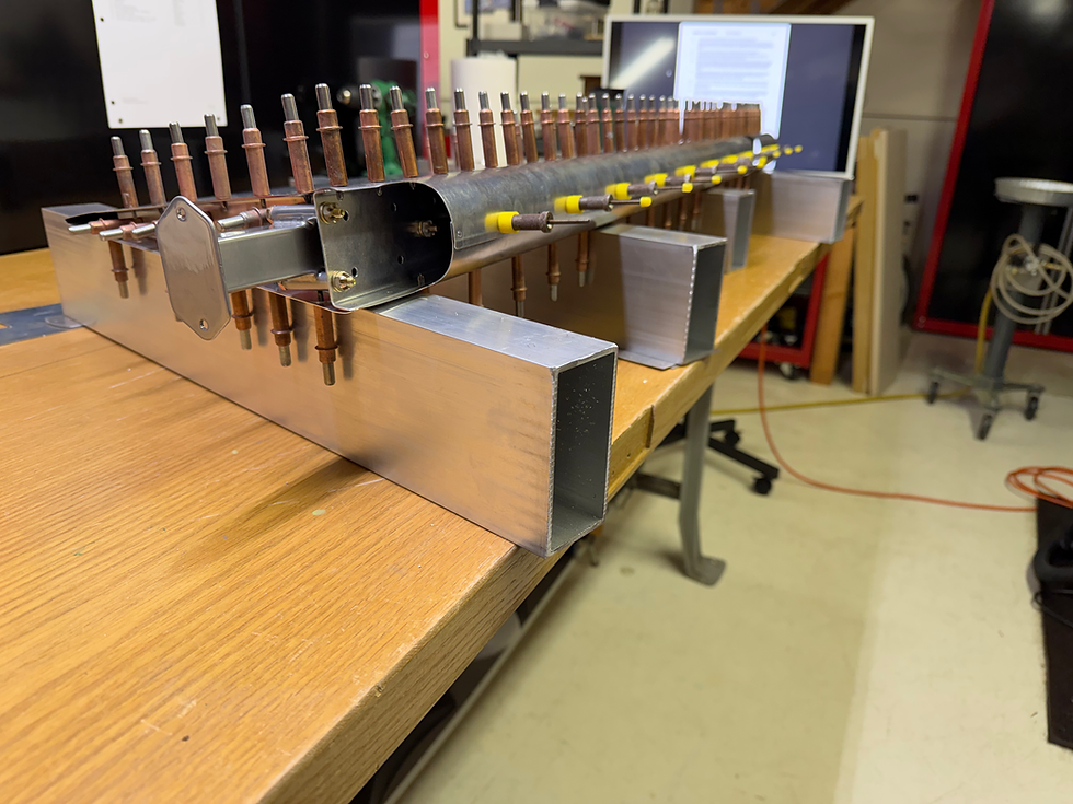
The last thing they have you do is drill the holes on the leading edge, the holes used to roll the skin, which are also used to rivet the two halves together, out to #30 in preparation for drilling.
To hold the front halves together I used what Pan American Tool calls "Knurled Cleco Fasteners". Others call them "Skin Pins". They fit the hole better and hold tighter than regular clecos and work well where additional hold is required.
Most people just use a #30 drill to enlarge #40 holes to #30. I am not most people. Of course, I used to do that as well, until I learned about Piloted Double Margin Drills. As the name implies, they have a pilot that is smaller than the main size. In this case, it is a #40 pilot with a #30 drill. The pilot goes into the existing hole without having to worry about the drill wandering.
At this point, all that is left is to take it apart, deburr everything and get it cleaned up and ready for a protective coating, more on that in Part 2.
Once I got it apart, I remembered about one other change I made form the plans. For mounting the Rudder Horn Mount Tube, which is held to the spar with three AN3 bolts, where there is a gap at the top mount hole, they tell you to use a stack of 5 washers to take up that space. Sure, that works, but it is hardly elegant. Fortunately, I have at my disposal a large assortment of aluminum and steel spacers of varying sizes and diameters. They general come in only two sizes; too small and too big.
I was planning to find one as close as possible and modify it to fit, either by drilling out the hole or shaving some off to get the right length. Much to my surprise, I found one that fit almost perfectly. It was larger than the 5 washers by only a couple of thousandths. That was close enough, without a micrometer or caliper, you'd never notice they weren't the same size.

Stay tuned for the exciting conclusion to HOW TO BUILD A RUDDER IN F EASY WEEKS.


Comments