
RV-8 and the 2026 Condition Inspection, The Part That Comes Next
- Steve
- 2 days ago
- 13 min read
To see where this whole saga began, you can look here. At the bottom of each post is a link to the next post in the chain until, of course, there are no more posts.

OK, so I won't keep you on the hook any longer. The tool that I thought would solve my problem in a jiffy was the Engine Mount Alignment Pins from Aircraft Tool Supply.

4/17-- 4/18/26 As it turns out, I never even got to give them a try, thanks to UPS. For the past several years, anything I have ordered from inside the continental US when ordered over the weekend and shipped on Monday would be here on Thursday via UPS ground. Based on that, I figured that I should get them on Thursday 4/16/26. Fate, through UPS, had a different idea.
As soon as they shipped on Monday I got an initial email from UPS stating that they would be delivered on Friday 4/17/26. This did not make me feel good. After I got over the shock and the anger, I worked a few things around and figured I could make that work. Also, they have actually delivered something a day earlier than originally quoted. Not often, but occasionally. I spent the week hoping that it would happen this time, but those hopes were dashed when Thursday came and went with no delivery. On Thursday I got an email confirming that they would be delivered Friday between 10:00 and 2:00. I still held out some hope that it would be earlier rather than later. Of course, they took the opportunity to dash those hopes as well.
A little before noon on Friday I got an email that they had "rescheduled" my delivery and it would now be delivered on Monday. That made me feel less than wonderful. Once I stopped cursing their name, which took a while, I decided to act on something that my Dad had suggested last weekend and just make my own. So I did.
I took a 7/16" bolt and cut the threads and head off to use as a blank. The main problem that I had was that I had no idea how long it needed to be. It needs to be long enough to hold the various parts in alignment but no so long that it hangs up on the dipstick opening on the crankcase (it will make sense, maybe, when you see the picture a little further down this post).

It took a couple of attempts to get the dimensions right, but it didn't take as long as I thought it would. I just used a hacksaw to cut the section to length. To get the taper I chucked it into a drill motor and spun it while grinding on it with a 6" disc sander. It was kinda cool to see the sparks fly. The 60 grit disc actually made short work of tapering the pin. The first time I tried it I tried for dimensions, or proportions at least, like the store bought ones above. It quickly became evident that that was far to thick at the pointy end. I needed to make the point much pointier that the ATS tool. It also took a couple of tries to get the length right.
With the newly forged tool, well not really forged, mostly just sanded, in hand, I headed to the airplane with very high hopes of quick and easy success. Because of the mismatch of the holes, it was not possible to just jam the tool into the hole. Once it got started in the hole it was necessary to pull the tool over to move the rubber piece to get the hole to line up. The problem with that is that with the tool short enough to make it out of the case successfully, there was not enough to grab on to once it was inside the mount half. Fortunately, the old mount had a spacer between the two mount halves that was the perfect size.
The mounts that came out were Barry mounts. I think the part number is, but don't quote me on this, 94011-20. As mentioned in the previous installment, I am using the Lord P/N J-9613-40 mounts. The main difference between the two is the bit that goes between the mount halves. On the Barry mounts there is just a straight spacer, but on the Lord mounts there is a spacer that has a gel-filled sac around it. They do the same thing, I just hope the gel doesn't escape. Apparently that gel filled center adds a slight increase in vibration damping over the Barry. We'll see.

In order to manipulate the bullet, I put the old spacer over the exposed end so that I could move it around as necessary and then used a 3/8" bolt through the other end to tap the bullet into place.

As I inserted the bullet into the hole, I had to tap it very gently to get it precisely located. I wanted it to be far enough in that there was a small space behind it so that the new bolt had a place to sit. In theory, it should have been just a simple tap on the bolt to push bullet through leaving the bolt in the proper hole.

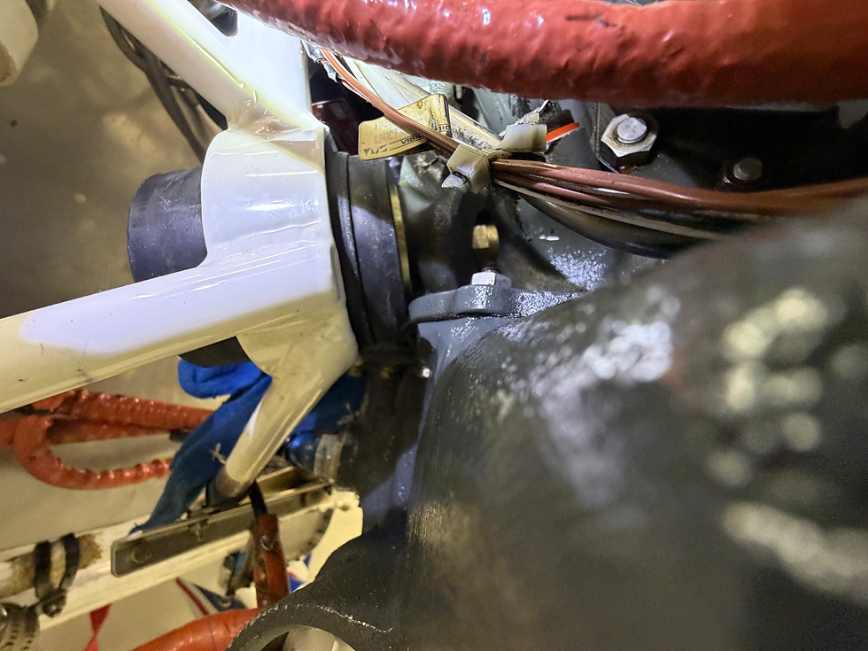
As promised earlier, here is a shot showing the reason that the length of the bullet is limited.

As you can see in the photo above, that bulge in the case really gets in the way. You can also see a bit of a scratch form an early attempt to get the overly long bullet out. After that, the little piece of aluminum foil tape seen the picture was placed between the emerging bullet and the case. Fortunately, that provided enough protection to keep from doing further damage.
As so often happens in the real world, there was a bit of a gap between theory and reality. In this case, that gap was about 1/8", very much the thickness of the big washer that goes between the mount half and the case on the bottom.

Since this is all a rather tight fit, each tap with the hammer only moves the bolt / bullet a very small distance. What usually happens is that the first tap, even a relatively solid tap, only moves the train 1/16" or so. Ordinarily that wouldn't be an issue, just tap it a few times and be done with it. Right. The first tap moves the bullet from the mount to the washer, but at the same time is no longer holding all three pieces; mount, washer, case at the same time. The tension from the rubber in the mount immediately moves the mount out of alignment with the hole, before the bolt can make the full trip.
Naturally, I assumed that this only meant that a bigger hammer was needed to make the train move farther on the first tap. I got a 2 LB hammer in there and the same thing happened. If I had a clear enough shot with the hammer, I might be able to make it work, but I am not so sure now. This lack of progress caused me to fall back and regroup. This is the point at which I would admit defeat and read the instructions, Sadly, for this operation I could find no instructions. Carl did, however, send me something written by someone facing a similar dilemma, though he was doing an initial install rather than a mount replacement. Many of the same principles apply though. There is nothing in the document stating who wrote it or where it came from, but I found it helpful. In particular, I found step 8 toward the bottom to be helpful.
I was trying to set the rubber mounts in the cups in the steel mount and then install the bolt. This guy did it the other way around. He got the two mount halves lined up so that the bolt would go in, then he worried about getting the rubber mounts into the cups in the steel mount.

This method required starting with the engine tilted enough so that the forward mount halves were loose and able to sit outside the cup. After some fiddling, though way less than I had invested so far, I was able to to get the bolt into the hole. From this point, I pretty much had to get the other side to the same point before I tried to get the mounts seated in the cups.

Once I got to this point, I feared that I would have the same difficulty as before since one is trying to do essentially the same thing, get the rubber to move out of alignment to match the alignment of the mount and case. In this case I used a block of wood and a BAM (Big A** Mallet). I only had to whack it a few times and the mount dropped right into the cup, more or less. With the amount of tension on the assembly and with the weight of the engine on the mount, it took relatively little persuading to get the rubber mounts to find their proper positions inside the steel mount.

Getting the nuts started wasn't too difficult, all things considered. At this point, I was very relieved. I was seriously beginning to worry about what I would do if I could not get this back together. It was getting late and I am a couple of weeks behind already, so I really needed to get the top ones done also. Through the whole process I had been consoling myself with the hope that the top ones would be much easier than the bottom.
With the bottom bolts in and nuts just started, I pulled the nuts off of the top mounts and removed the bolts. Before I moved the engine at all, I wanted to see what the alignment looked like before I moved anything.

When I got the top left bolt out, I was very surprised to see that the hole was very close to aligned. Maybe this will be easy after all. Once I got the top right out also, I lowered the front of the engine to allow me to get the forward half out. Since the rubber mount goes in the top the opposite way of the bottom, with the larger half between the mount and the engine, I feared that I would have to lower the engine a lot and there were some lines that had very little slack in them. As it turned out, it didn't have to come down as far as I thought it would and the weakest point was just at the maximum tension I was comfortable with when I was able to get the old ones out and the new ones in.
Of course, before I put the new ones in I cleaned the cups and looked everything over very closely. Fortunately, I found no cracks or other damage.
The top went in much easier and I was amazed at how quickly I got them in. After taking more than two weeks to get the bottoms changed out, I had the top ones swapped out in just over an hour. Wait, what is that? Why does the left top look wrong? Curses! I left big washer that goes under the head of the bolt out. Bummer dude. How do I get that fixed. What? I have to take both of them back out and start over? Really? Yes, really. OK.
So, I had to take them out and start over with ALL of the new hardware installed. The right one went back fairly easily again. The left one, not so much. The aft half was easy to convince to go in with my BAM and wood block. The forward half however, not so easy. On the left side, behind the #4 cylinder resides the oil cooler. The rear baffle has a ninety degree bend right at the same place and the forward mount sits in the corner that it forms. There is no room to get the stick in there, let alone hit it with a hammer. I tried, very gently, to pry against the corner of the oil cooler, but it was immediately evident that the oil cooler would be damaged before the mount popped in.

Just when I thought I was once again stuck with no way out I had a brainstorm, I mean an idea. Why not wrap a cargo strap around the whole steel mount and pull it in? Why, because that's just plain crazy,m that's why. You can't use that bubba engineering on an airplane, it's not done. Oh yeah?

I knew that if this required too much force I stood the real danger of damaging something.

I didn't want to ratchet it too tight and just as I got it snugged up I tugged on the part of the strap going around the left mount and you know what? I heard a loud POP. I ran over to the other side and it had moved most of the way into position. I tired it again and got another pop and it was in place.
One of the things I learned about this method is that you can easily hear when these things pop into place. I was able to hear as each one dropped in, It was kind of a loud scary sound, but it soon became a comforting sound.
Now with what I truly hope is the hard part behind me, the next step is to get the washers and nuts on the bolts. Fortunately, this step is not too difficult, though access on the bottom is minimal.

At this point I disconnected the engine hoist, since it wasn't needed anymore.
For my next trick, I will pull a rabbit out of my hat... Wait, no that was Bullwinkle. I will tighten the nuts and then torque them. Easy task says you, not at all easy says I. How are you going to hold those nuts? Castellated nuts, like those that came off, do not require a lot of force to tighten. Metal lock nuts, such as the MS20365-720C that was supposed to be in the hardware kit from Van's, or the AN363-720 nuts that actually came from Van's, are much harder to turn due to the self locking feature. These are also much harder to turn than Nylock nuts.
The bottom ones aren't that hard to do because the box end of a combination wrench will fit over the nut and into the recess in the case. The top ones on the other hand. Well, the top ones are a different story altogether.

The left side wouldn't be any harder than the lower ones, the box end of a combination wrench would fit here also, but for one thing. The push rod housing that sits right, and I mean RIGHT in front of it. The one above was scratched before I started, probably from whoever put it in in the first place. The open end of the combination wrench, or any other open end wrench won't work, at least not at the torque required. There is simply not enough meat for it to grab on to. I think I may still be able to do this one. I think if I grind down the box end of a combination wrench I can get it in there. My Craftsman wrench is just slightly too thick. I'm fairly certain that I can find a junk wrench that I can use to make a tool that will fit.

The right side, now this one is truly going to try my patience. With the baffle where it is, there is no room to get a box end on there. I may be able to grind down an open end enough that it will hold. After all, it only has to work once. In any case, I see more grinding in my future.
4/19/26 First thing today I found a wrench from an old emergency tool kit that I definitely had no qualms about grinding on.

Because I was certain it would be the easier of the two, I started with the left top mount. As previously mentioned, a box wrench almost fits on this side.

I began grinding in the box end of my chosen implement. It was already thinner than my Craftsman wrench, so it should take less grinding. After a few minutes on the sanding disc, I had it to where I could get the box end onto the nut.

I thought I was golden and started torquing on the bolt. Once I had it tightened, I noticed what I had failed to consider before. Now that it is tight, the bolt sticks out of the nut a couple of threads, eating into the clearance that I thought I had. Now I couldn't get the wrench off. I thought briefly about just leaving it there so that it would be available for the next time it had to come off, but rejected that idea. Great, now I have to loosen it up again and grind off some more. After another few minutes on the sanding disc I was able to tighten the bolt and retrieve the wrench for later use.
Since that didn't take as long as I thought it would, I felt a little better about the last nut I had to get to. Since there was no way to get a box end wrench on this one, I had to grind away some, OK, a lot, of the open end end.

Once I had all of the bolts snugged up it was time to get out the torque wrench for the final tightening. I have enough experience that I am comfortable just using my calibrated elbow on most fasteners, but on important ones, I use a torque wrench. Important like, you know, the bolts that hold the engine on, or the landing gear on, or the wheels together, and even the spark plugs.
The specification for an AN-7 bolt is 450-500 inch pounds. That is the figure for standard nuts (AN310, AN315, or AN363). In this case, I am using a metal lock nut (MS20365 / AN363). Those nuts add a lot of drag so I wanted to measure the running torque, which is supposed to be added to the torque specified to get the proper actual torque. I measured the running torque at about 80-90 inch pounds, so I set my torque wrench for 550 inch pounds which should get me right in the middle of the specified range.
Since these nuts do not use cotter pins, there is no quick visual indicator of whether or not they are still tight, so I added some torque seal to both the nut and the bolt so I will be able to see if either one turns.
Once that was done, I was officially finished with the replacing the engine mounts section of the program. It is now time to put back together everything I took apart to be able to get access. I started by putting the last two (#3 and #4) intake tubes back in with new O-Rings.
I finally feel that I had a good weekend's worth of work and was able to check off two of the most major items from my list of things to do. Once I have everything put back together, it will be time to get back to the actual condition inspection. I hope to finish up the firewall forward section next weekend.


Comments