
RV-8 and the 2026 Condition Inspection, Part IV
- Steve
- Apr 12
- 7 min read
Updated: 2 days ago
If you're new to this saga, and are of a mind to, you can go all the way back to the beginning here and learn all that has happened. At the end of each post is a link to the next post in the series.
Friday 4/10/26. I took Friday off since I seem to be falling further and further behind.

When last we left our stalwart hero, he, I mean I , was trying to get the cotter pins out of the engine mount bolts. The lower left one was quite difficult and took entirely too long to get out, and at that, it came out in pieces, but it did come out. As a result, I spent the whole week fairly anxious about how I was going to get the rest out. OK, it was really only the lower right that had me concerned, I was pretty sure the top would be easy, or easier anyway.
If the left was was almost impossible to get a tool on, the right was was almost impossibler. I was really struggling to figure out what I could use to get it out when I remembered something that I had dismissed for may years. There is a tool made specifically for extracting cotter pins. I have known about them for a very long time and never even considered buying one as I thought a "real mechanic" didn't need such a gimmicky tool. Well, it just so happens that there are times when no other tool will fit and this little guy turned out to be just the right thing.

To my surprise, and great delight, this was just what the doctor ordered and made short work of that pesky right lower cotter pin. The left upper was truly a piece of cake, it came right out with no argument at all. The upper right, on the other hand, while not as hard as the right lower, it was close.
On the three other bolts, the bolt would rotate easily allowing me to get to both ends of the cotter pin. This one would only rotate in the loosening direction. If I tried to turn it the other way, it would just tighten. The nut seemed to be corroded in place. The whole thing was much more difficult to turn than the others. This one too came out in pieces, and I had to fish a piece out of the cooling fins, but it did come out.
With the overture out of the way, it was time for the symphony. My plan was simple, or so it seemed. I thought it would be best to start on the bottom mounts, mostly because I thought they would be the hardest and hopefully, with them out of the way, it would be downhill from there. In order to get the mount pieces that go between the steel engine mount and the engine case out, I would have to remove two bolts, in this case the bottom bolts, and slightly loosen the top bolts and use the engine hoist to lift the front of the engine up to create the clearance needed.

The theory being that at all times the engine would be supported by two bolts and the crankshaft, so that hopefully it wouldn't end up on the floor.
As I started removing the bolts and preparing to lift the engine, I was nervous because I couldn't see the whole engine and worried that something would shift that I couldn't see. I felt it prudent to have another set of eyes on hand to help out, so I planned to wait until Saturday when Carl came by to help me.
Since I still had some daylight left, I decided to start on the tail by disassembling, cleaning, greasing, and reassembling the tail wheel. There is no grease fitting on the tail wheel, so the only way to get grease to the pivot bolt is to take it apart. This should be done every 100 hours at least, and other some conditions possibly more frequently. I didn't fly as much since the last condition inspection as I would like to, so it hasn't been done since then. That took me to the end of the day.
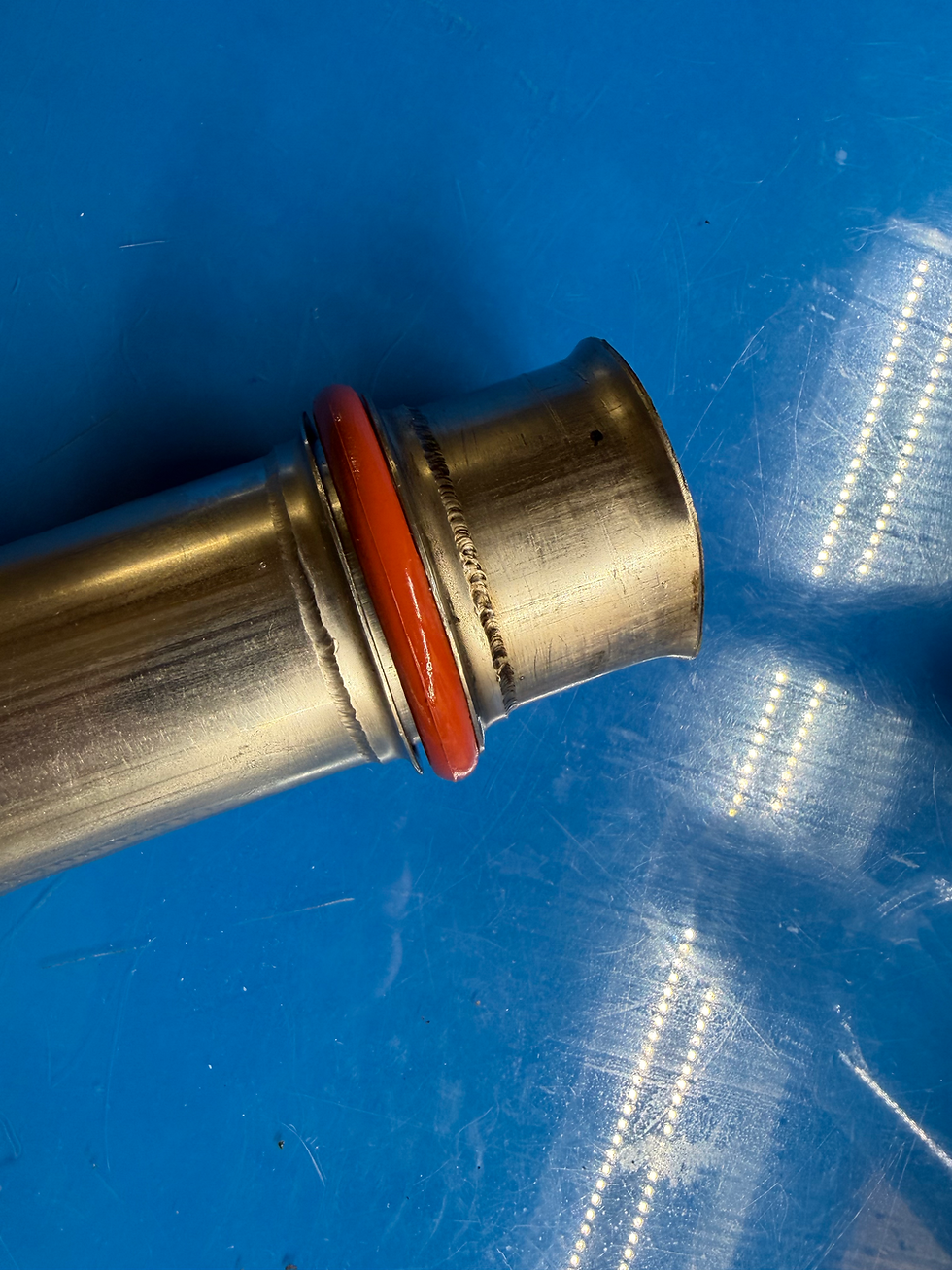
Saturday 4/11/26. I came out early to try to get some stuff done before Carl got here. I put new upper and lower O-Rings on both forward, #1 and #2, intake tubes. I took them out one at a time and cleaned them and installed new O-Rings. As mentioned in part three, I used DC 4 on the O-Rings. That worked well for installation, hopefully it will be someone else's problem by the time they need to come out again.

This engine is somewhat different than most Lycomings in that this intake tube has a groove machined in for an O-Ring. On standard Lycoming engines, they have a flat flange and use a paper gasket. This is one of the modifications that was done by Ly-Con when the engine was but a babe. It was delivered from Van's directly to Ly-Con for modification before being delivered to the builder. Among other modifications that were made was the installation of 10:1 ceramic coated high compression pistons, conversion to fuel injection, conversion to a constant speed prop, among others. With all that, they also installed a cold air sump from an angle valve 306, that is where these tube came from.
On e thing of note, that was learned the hard way, is that with this modification, the paper Lycoming gaskets will no longer work, they will leak. There is empirical data to back it up.
Fortunately, the bottom end uses standard Lycoming O-Rings.
Just before I put number two back in, Carl showed up. After doing our standard Saturday morning BS session over coffee, we got to work trying to change the mounts. I loosened the top two bolts and began removing the bolts from the bottom. Fortunately, with the bottom, the weight of the engine is pushing down on the mount, so the front doesn't really need to be supported until ready to take the actual mount bits out.
It took a little bit more doing than I expected, but I got the bottom bolts out. Once they were out, we gently raised the front of the engine. This part worked much more easily and seamlessly than I had dared hope for. The engine rotated just as I hoped it would and, though I had to go higher for the left side than for the right, in short order I had both front bits out.
I am using the Lord J-9613-40 mounts. There is also a Barry mount, which it turns out is what was in there before. The Barry's are about $60 bucks each less than the Lord's. Which are better? One could easily say, whichever one is in stock. I had heard of some problems with the Barry's, but if I had known that was what had been in there for the past 25 years / 2,500 hrs, I probably would have bought them again.

It is a little confusing to figure out how these go in as there is no front and back. What is the front and what is the back depends on where it is going. The short piece, J-7763-1 in the figure above, is the front on the bottom, but that back on the top. It makes sense if you think about it. Gravity being what it is and all, the load is carried by the front face on bottom from the engine case sitting right on the mount, but on the top, the load is carried thought the bolt and to the back side of the mount.
Getting the rubber piece in was, as previously mentioned, quite easy. At this point I was near giddy thinking that this would be an easy day. Oh silly me. As they say in the Navy at BUDS (Basic Underwater Demolition Seal), basically SEAL boot camp, "the only easy day was yesterday". The same appears to apply in aviation maintenance.
When I went to install the bolt on the right side, reality came crashing back in on me. As it turned out, the whole thing was off by about half a hole. It is a 7/16" bolt, so half of that should be somewhere around 7/32". which doesn't sound like a lot until you can't get a bolt in.

I know what you're thinking, you're thinking that is is the extra washer on that side on the bottom that is in the way. I wish you were right, and both Carl and I had the same idea, bit that is not the washer, that is the hole in the engine case.
We tried several combinations of lifting the engine, lifting in a different location, prying on stuff and anything else we could think of, and none of it worked. The only thing that got it to line us was to put a drift in the hole and pull it to one side. That worked well, but there is no way to get the bolt in with the drift in the hole.
At his point I could think of no other alternatives and I know from experience that this is the point, when frustration hits and extreme force is contemplated, that things go from bad to worse, often with expensive parts being damaged, so I knew it was time to drop the tool and back away from the airplane.
Just as I was about to admit defeat and head home to lick my wounds, I remembered something that I had read somewhere, sometime, about a little gizmo that was designed for this very purpose. To find out what that thing is and if it works, tune in next week, same Bat time, same Bat channel.


Comments