
RV-8 and the 2026 Condition Inspection, Nearly Done
By nearly done, I obviously mean 90% complete with 90% to go.
To see how this whole process came about, you can read about it here. There is a link at the bottom of each post to the next post in the series.

5/9/26 - 5/10/26. After making much progress last week, I was finished firewall forward as much as I could do until I get the propeller back. That just left the rest of the airplane to do. Well, I had already done the tail, so that was out of the way. I still had the fuselage and wings to get through.
One of the first things I wanted to knock out on the fuselage was Van's SB 16-12-16 regarding some possibly missing bolts in the wing center section of Quick Build kits. This SB came out before I bought the airplane and I know that Carl told me that he had Chris check it when it first came out and there was no hardware missing. In looking through the log book tough, I couldn't find it addressed anywhere. I wasn't too concerned about that, it is easy enough to look at, as long as the interior is removed, so I grabbed a mirror and a flashlight and went to have a look.

The problem that I immediately faced was the fact that I wasn't faced with any bolts. I was quite confused because I didn't see any bolts, but I didn't see any empty holes either. There were rivets in all the holes that are called out. The SB says nothing about rivets.

I wasn't worried about it, having rivets in there is just fine, I was just puzzled. As I got to cogitatin' on it, it hit me that this is a very early RV-8 quick build kit and it may have even been built before there was a tricycle gear option available. That would certainly explain why the factory put rivets in those holes. They are the holes where the main gear attach weldments get mounted on the tricycle version. That is why they are not filled at the factory, so the same fuselage can be either conventional or unconventional.
I remembered that Carl and I had talked about this before I bought the airplane, and he emailed me about it shortly after I bought it. What I didn't remember was the whole rivet thing. As it turned out, Chris saw the same thing but wanted something from Van's stating that it was OK. Van's confirmed that it must be an early kit and that the rivets were fine.
Once that was settled, it was just a matter of inspecting and lubricating the wings and fuselage. I got that completed without any further complications and am now ready for the prop. I was really hoping that I would get a call the week of 5/11 and be able to pick it up on 5/15 but, alas, that did not happen.
I started getting nervous, so on Thursday I called and asked for an estimated completion date. I was told that they hadn't started putting it back together yet, but that everything was ready to go. They got a whole bunch of stuff ready to assemble at the same time. That makes sense since there were quite a few props received at the same time as mine. He said that he would start putting it together either Friday or Monday and that I could pick it up next week. I reiterated that I was more interested in it being done correctly than quickly. The bad thing about that schedule is that it will have me driving down to Seattle on the Friday before Memorial Day, a notoriously heavy traffic day. I was also told that they just got my governor back earlier in the week, so at least I can get it all at the same time. To be fair, when I dropped it off I was told it would be 6-8 weeks and next week is 8 weeks. If completed, it will be right in the time frame they quoted up front.
5/16/26 - 5/17-26 - That left me wondering what I would do this weekend. All of the sudden I had nothing pressing. The only thing that I really had left that I wanted to do was inspect the wheels and brakes and lubricate the guide pins for the calipers, and clean the belly. That was easy enough to do and didn't take too long to accomplish. I checked the tread depth on the new tires that I put on in October of last year and the brake pads and they are both wearing well with lots of material left, so they shouldn't require much, if any attention in the coming year. I also put air in the tires and was a little shocked to see that they were both down to 40 PSI. When I put the new tires on I filled them to 50 PSI.
I spent the money for the Michelin Air Stop tubes that don't leak as much a regular tubes. In this case, they went down 10 PSI in 6 months. That still is pretty good, but usually it is more like 5 PSI in that time frame.
With little else to do before the prop arrives, I decided to get ready as much as I can. I cleaned up the flywheel and prepared to put it back on.

The flywheel wasn't too dirty, but it had been on there for 25 years and definitely benefited from a few minutes oi cleaning. The photo above shows the forward face, the side that attaches to the propeller. Now that they are clean, the timing marks are a little easier to see.
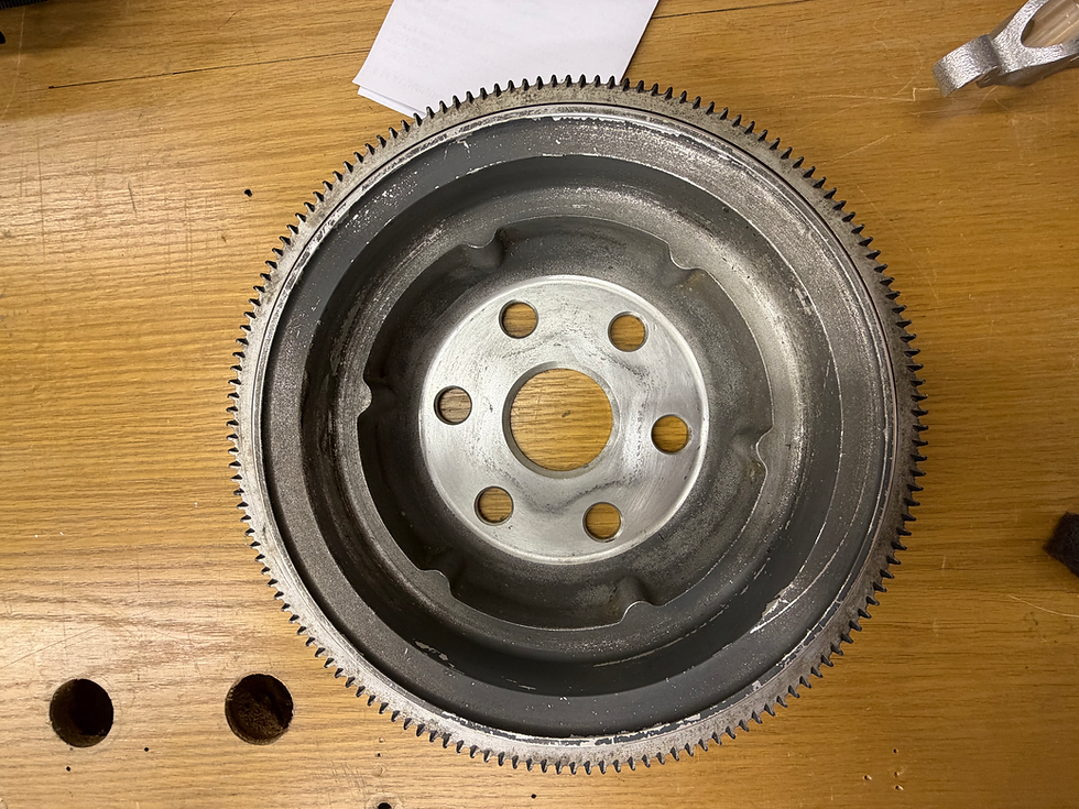
As I was cleaning the inside, or the side that mounts to the crankshaft, I had a little bit of a panic attack as I saw what looked for all the world like cracks down in the bottom of the wheel. They had the kind of jagged appearance that instantly looked like cracks. The only thing is that they were in an odd location for cracks and there were a lot of them. That seemed highly unlikely.

One of the first rules of inspecting is that cracks don't wipe off. If a mark wipes off, it can't be a crack. I took a paper towel and some alcohol and rubbed at the marks and, lo and behold, they disappeared. Turned out to be just some weird looking dirt deposits. That was quite a relief.
From there I wanted to stage the flywheel on the crankshaft in preparation. This led to the next potentially fatal flaw with my disassembly process. When I took this off, I forgot to mark its orientation I did mark the spinner bulkheads). As I looked at it, I had no idea how it was situated. It is not indexed, so it will go on many ways. At first I thought that it must not matter, but then I said, "whoa, of course it matters, if it is not properly installed the TC mark will not line up properly when the #1 cylinder is at top dead center on the compression stroke, which would make timing the mags virtually impossible".
In order to get everything back on the way that it came off, I was very careful not to rotate the crankshaft while it the prop off. Now, I thought the only way I could get this back in the correct orientation would be to rotate the crankshaft until the #1 cylinder was at top dead center on the compression stroke, then align the TC mark with the timing mark. I really didn't want to rotate the crankshaft, and then have to put it back where it was. Then I remembered the pictures.
Before I took everything apart, I took a lot of pictures, hoping to preclude just such a situation as I now faced. I went back through my pictures and, sure enough, I had a couple of pictures showing the orientation of the flywheel before removal.

When removing the propeller, The flywheel was rocking back and forth and creating a nuisance, so I subdued it with a couple of zip ties that will hold it in place until the bolts can be tightened. I also pleased myself in that I remembered to install the new alternator belt when I put the flywheel back on. That would have been a real mess to get the prop back on only to notice that there was no belt. The belt cannot be installed with the prop and flywheel installed, they would both have to come off again. Bullet dodged.

One other thing that I thought about this week that had been in the back of my mind since this whole thing started was that the front bulkhead for the spinner would need to be modified in order to get it back on.
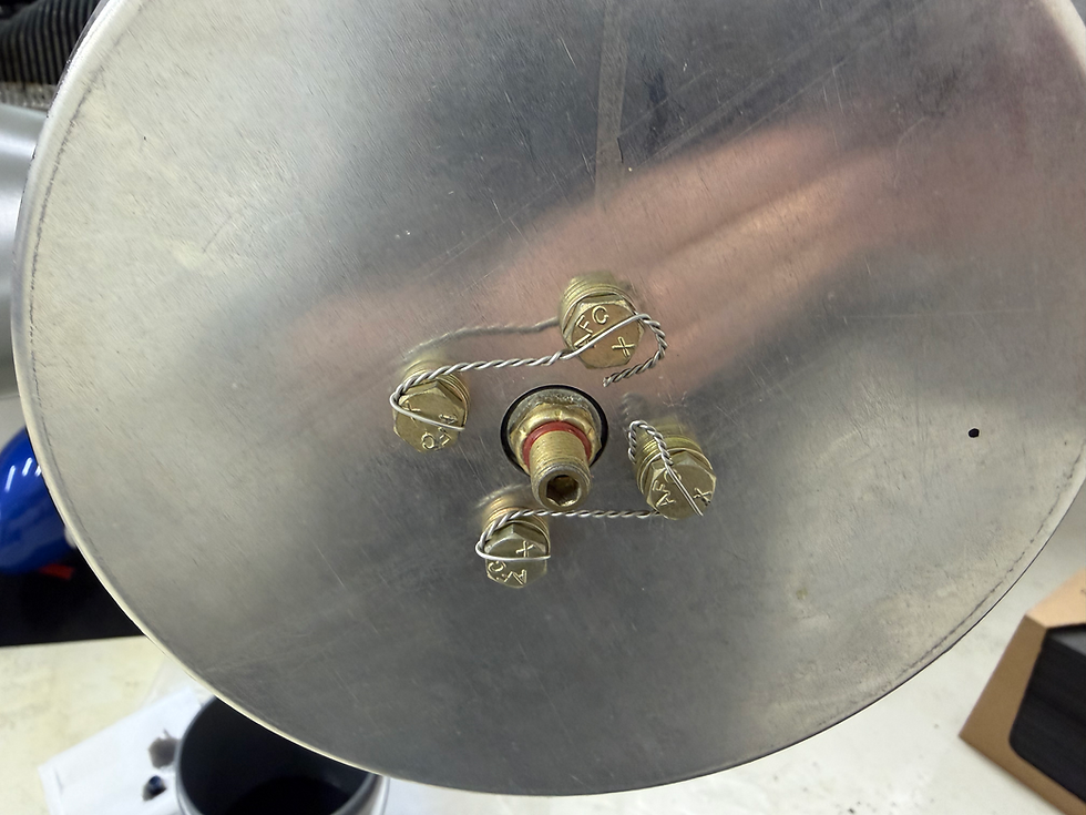
I have read in various places that when a prop is disassembled, it is nigh on to impossible to get it back together with these four holes in exactly the same place as when it was disassembled.

Many people say that they are close, but don't quite line up. In order for the spinner to fit, this bulkhead must be in exactly the same orientation as it was before. If the holes are close, one can cut a slot to allow for alignment, but if they are off by a lot, it might be necessary to locate and drill new holes. I spent a lot of time thinking about how I could cut a slot, since it is not in a straight line, but in an arc. I think I figured out a way and decided to start trying to set up for it.

To begin, I wanted to capture the two circles made by the inside and outside edges of the bolt holes. I figured that with those, I could put it on the mil and see if the cutter moves within those lines and would make the arc I was looking for.
Once that was done, I figured out that I actually needed them on the other side so that I could mount it to the rotary table on the mill. After redoing the lines, I mounted the rotary table to the mill table. That was the easy part. The less than easy part was figuring out how to mount the bulkhead to the rotary table.

The first challenge is that the bulkhead is almost the same diameter as the rotary table, leaving basically no room to clamp it down. This was when I decided that I needed to flip it over and maybe have better luck that way.

By putting it up on a set of parallels I was able to get a little room underneath so I don't cut into the table. I tried to find a C-Clamp or something that I could work into the T-Slot to hold it in place, but nothing would fit. I was searching through the whole hangar trying to find something that would work. I found something. It is out of the ordinary and it may work, but it looks weird.

It looks like my Dad made some T-Nuts that were threaded, instead of having a bolt coming out of them, and I found a piece of threaded rod and a carriage bolt that were long enough and used a large washer to hold the bulkhead and a nut to adjust tension. It actually works and holds the piece firmly. I don't think it would hold up to a lot of force, but it is .050" or .063" aluminum, so it shouldn't take much force to cut a small groove.
The next conundrum was how to center the piece on the table. There is an aluminum disc at the center of the table with a 3/8" hole in it. A 3/8" drill blank fits very well. The problem is that the center hole in the bulkhead is much larger than 3/8". The ideal situation would have been to find a bushing, or something, that had an outside diameter the same as the bulkhead and an inside diameter of 3/8". Alas, I could find no such thing. That doesn't mean that such a thing isn't in there somewhere, I just couldn't find it.

What I did find, however, was a gear that had a flange that fit the hole perfectly. Alas, it's inside diameter was larger than 3/8". I did find a bushing that would fit that hole, but the inside diameter of the bushing was less than 3/8". By the time I drilled it out to 3/8" there would be very little material left. In this case, the fit was close enough that I could tell visually when it was centered. If I was going to be making a large cut or to groove the whole circle, I would want a little more precision, but for this purpose, I think it will work.
I put together a short video that I think shows my theory in action. With any luck, this will work out. Hopefully, I won't have to enlarge anything by more than half a hole.
With any luck, the next installment will show the installation and test run of the overhauled prop and be the final entry in this saga. So, tune in last week and miss next week's episode of PIG's, no wait, I mean Marathon Inspection.


Comments